
📌 Author(s): Roman Mayer, Markus Hoser 📌 Company: maku engineering GmbH 📌 Contact: rommayer@maku-engineering.com, marhoser@maku-engineering.com 📌 Technologies: MATLAB/Simulink, Simscape, Phoenix Contact PLCnext, Siemens Drives, Peter Corke’s Robotic Toolbox
Motivation: Why Teach-Free Path Planning?
In industrial automation, 2-axis gantries are widely used – from CNC machines and pick-and-place robots to material handling systems. The programming of these gantries is often done via teaching, meaning the operator manually moves the system to desired positions, saves these as waypoints, and defines a trajectory.
The Problem:
- Teaching is time-consuming and prone to errors.
- Changes in the environment or the system require relearning.
- Automated solutions are often expensive and require complex integrations.
Our Solution: We have developed a teach-free path planning system that eliminates the need for manual teaching processes. Instead, an intelligent algorithm automatically generates the collision-free trajectory.
Objective:
- Automatic path planning for a 2-axis gantry
- Use of MATLAB/Simulink & Simscape for modeling and simulation
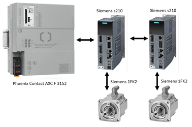
- Code generation for a Phoenix Contact PLC (AXC F 3152)
- Integration of Siemens SINAMICS S210 drives via Profinet
📌 Images/Visualizations can be found in the last section!
Technical Implementation
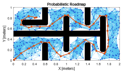
Our path planning system utilizes MATLAB's mobileRobotPRM algorithm to generate waypoints. This means:
🟢 Automated Path Planning
- The environment is represented as a map (matrix).
- Obstacles are detected and avoided.
- The shortest, collision-free path is computed.
🟢 Modeling in MATLAB/Simulink
- Simscape Multibody for the physical simulation of the gantry system
- Simscape Electrical for integrating Siemens servo motors
- Peter Corke’s Robotic Toolbox for path planning [https://github.com/petercorke/robotics-toolbox-matlab]
🟢 Code Generation & Control
- The planned path is converted into executable code for the Phoenix Contact PLC using Simulink Coder & Embedded Coder.
- The PLC sends trajectory points via Profinet to Siemens drives.
Advantage: The entire system can first be simulated and then directly transferred to the real hardware.
Additionally, we successfully integrated Siemens motors with Phoenix Contact support, without requiring extra licenses. This was made possible by using the Siemens inverter device description files (GSDML files) to enable Profinet communication.
Expansion Potential
Our system is modular and can be extended with the appropriate effort:
🔹 Replacement of the Mechanical Model and Adjustment of Drives
- The mechanical model can be replaced using CAD data, provided the necessary toolboxes are available.
- Based on the desired dynamics, the drive configuration can be pre-simulated to optimize performance.
🔹 Dynamic Environment Updates
- The current static map can be replaced by an image processing system.
- Cameras or LiDAR sensors could be used for environment detection.
- The map can be continuously updated during execution to account for moving obstacles.
🔹 Expansion to Multi-Axis Systems
- Currently, the system is designed for 2-axis motion (X/Y).
- An extension to 3-axis systems (X/Y/Z) is possible. This requires: * Adaptation of the mechanical model * Integration of a third drive, which must be incorporated into the path planning algorithm
Conclusion & Outlook
Our teach-free path planning enables: ✔ Time savings – No manual teaching required ✔ Flexibility – Environmental changes are automatically considered ✔ Easy implementation – Direct code generation for Phoenix Contact PLC
What’s next?
Parts of this project are based on an open-source repository and are freely available. Our enhancements and programs can be provided free of charge upon request. Of course, we are also open to a call if needed.
Depending on the interest in this blog post, we plan to:
- Offer this solution as a free app through this blog entry
- Publish it on the MathWorks platform
Questions, suggestions, or ideas? Feel free to leave a comment or contact us directly!
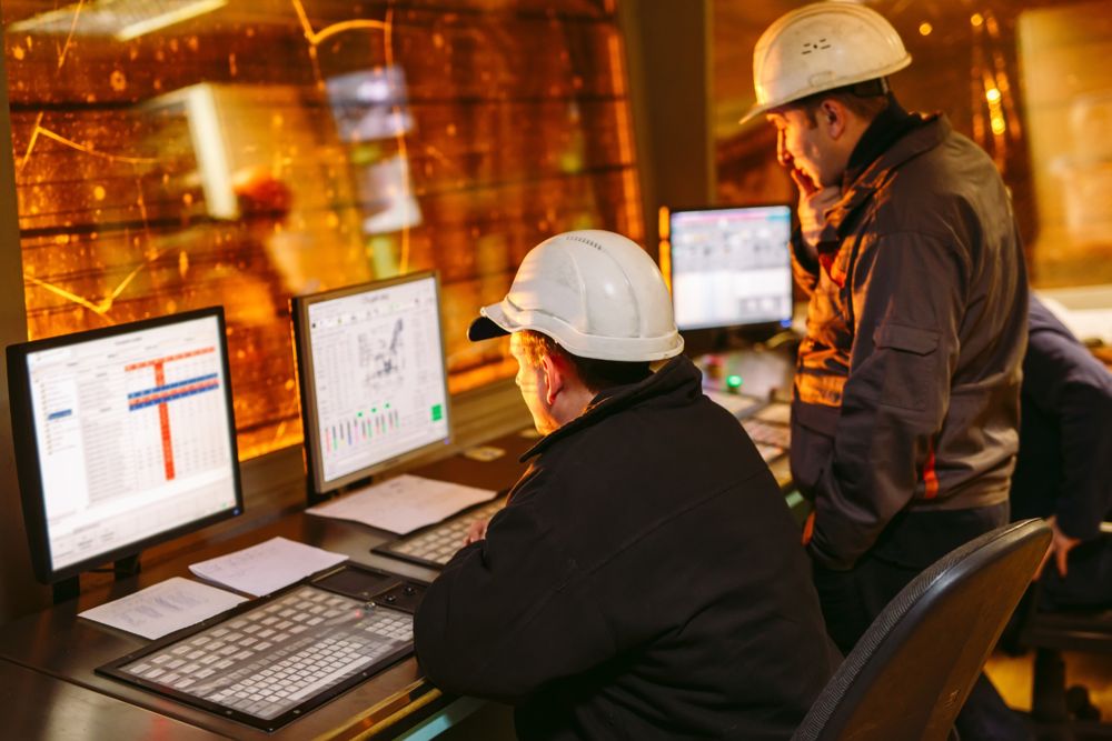
Hardware Setup / Impressions / Results
Our hardware setup consisted of:
- Phoenix Contact AXC F 3152 PLC for control
- Two Siemens motors for actuation
- Fully virtual mechanics – The entire mechanical system was simulated in MATLAB/Simulink & Simscape
The following map was used for execution/creation:
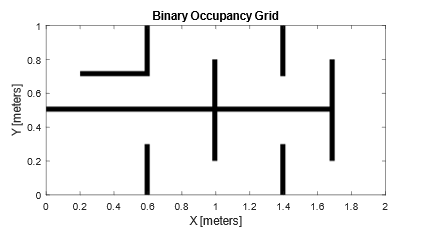
The width of the obstacles is adjusted according to the tool. Additionally, the automatically generated support points from the start to the target point are shown in red.
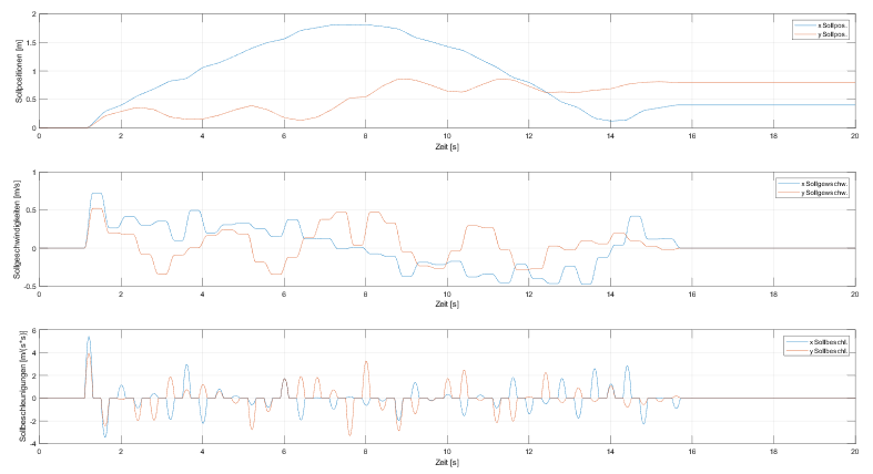
The stored waypoints need to be smoothed to achieve seamless transitions between different acceleration phases. Additionally, it is crucial that the path remains differentiable to prevent the motors from decelerating to zero speed.

The movement of both motors is synchronized, with their acceleration phases coordinated to ensure smooth operation.
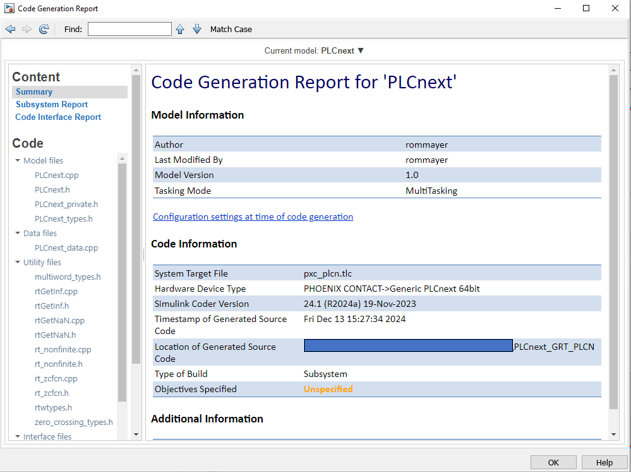
Finally, here is an image of the successful code generation of the submodel for path planning. The integration of the generated object can be carried out one-to-one following the descriptions provided by Phoenix Contact!
Leave a Reply
You must be logged in to post a comment.