AXC F XT SPLC 1000 (SPLC 1000)
Note: For further information about the hardware, refer to the product documentation of this controller (item no. 1159811):
Connecting and operating elements

The controller consists of the following components:
| 1 | Function identification |
| 2 | Bus base module |
| 3 | Electronics module |
| 4 | Supply connector (connector for connecting the supply voltage (communications voltage UL, 24 V DC)) |
| 5 | Diagnostics and status indicators |
Printing and test mark

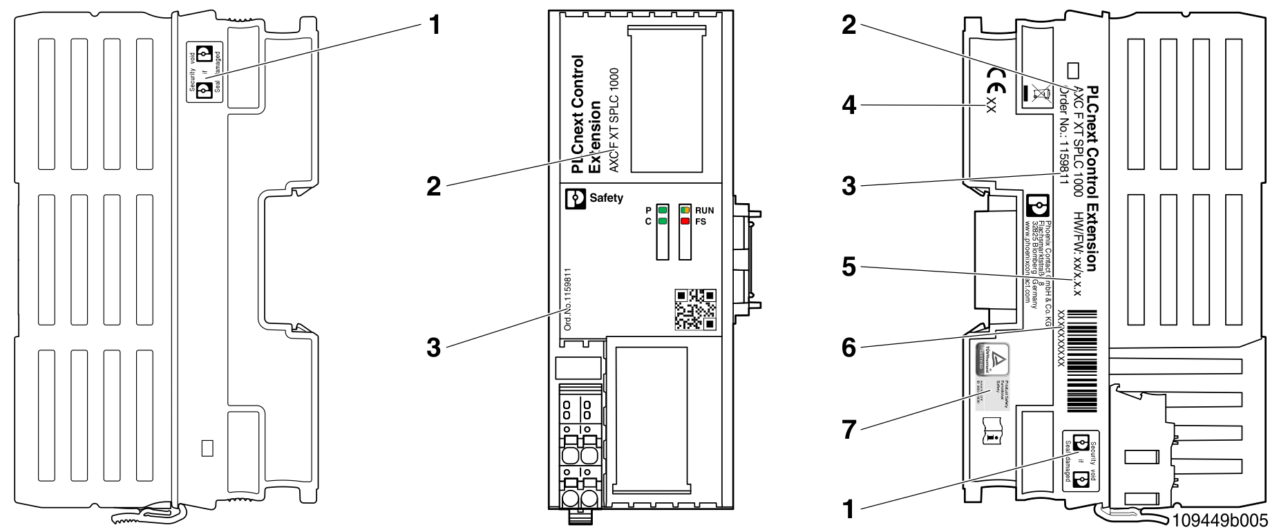
SPLC 1000 printing, including test mark:
| 1 | Security seals |
| 2 | Item designation |
| 3 | Item number |
| 4 | Year of manufacture |
| 5 | Revision versions (HW/FW) |
| 6 | Serial number |
| 7 | Test mark |
Diagnostics and status indicators

| LED | Color | Meaning | Status | Description |
| FS | - | Failure State: Safe state of the SPLC 1000 |
Off |
Error-free operating state of the SPLC 1000 with supply voltage present. A Failure State is not present. |
| Red | Flashing (1 Hz) |
The SPLC 1000 is in the Failure State due to a configuration error in the PLCnext Engineer software. The SPLC 1000 has switched to the safe state (Failure State). The SPLC 1000 can be accessed from PLCnext Engineer online. Note:
Remedy the error and perform a project download:
|
||
| On |
A critical error in the SPLC 1000 hardware has occurred and been detected. The SPLC 1000 has switched to the safe state (Failure State). Note:
Perform a voltage reset:
Or restart the standard controller in the PLCnext Engineer software:
|
SD card
- Only use encrypted SD cards!
Information on this can be found in the topic SD card encryption.
Controller-specific information on the 62443-4-2 compliance list
Note: Please note the additional controller-specific information on the 62443-4-2 compliance list.
• Published/reviewed: 2024-12-09 • Revision 015 •